Characteristics
One advantage of electrification is the lack of pollution from the locomotives themselves. Electrification also results in higher performance, lower maintenance costs, and lower energy costs for electric locomotives.
Power plants, even if they burn fossil fuels, are far cleaner than mobile sources such as locomotive engines. Also the power for electric locomotives can come from clean and/or renewable sources, including geothermal power, hydroelectric power, Nuclear power, solar power, and wind turbines. Electric locomotives are also quiet compared to diesel locomotives since there is no engine and exhaust noise and less mechanical noise. The lack of reciprocating parts means that electric locomotives are easier on the track, reducing track maintenance.
Power plant capacity is far greater than what any individual locomotive uses, so electric locomotives can have a higher power output than diesel locomotives and they can produce even higher short-term surge power for fast acceleration. Electric locomotives are ideal for commuter rail service with frequent stops. They are used on all high-speed lines, such as ICE in Germany, Acela in the US, Shinkansen in Japan and TGV in France. Electric locomotives are also used on freight routes that have a consistently high traffic volume, or in areas with advanced rail networks.
Electric locomotives benefit from the high efficiency of electric motors, often above 90%. Additional efficiency can be gained from regenerative braking, which allows kinetic energy to be recovered during braking to put some power back on the line. Newer electric locomotives use AC motor-inverter drive systems that provide for regenerative braking.
The chief disadvantage of electrification is the cost for infrastructure (overhead power lines or electrified third rail, substations, control systems). Public policy in the US currently interferes with electrification—higher property taxes are imposed on privately owned rail facilities if they have electrification facilities. Also, US regulations on diesel locomotives are very weak compared to regulations on automobile emissions or power plant emissions.[citation needed]
In Europe and elsewhere, railroad networks are considered part of the national transport infrastructure, just like roads, highways and waterways, and therefore are financed by the state. Operators of the rolling stock pay fees according to rail use. This makes possible the large investments required for the technically, and in the long-term also, economically advantageous electrification. Because railroad infrastructure is privately owned in the US, railroads are unwilling to make the necessary investments for electrification.
[edit] History

Alco-GE Prototype Class S-1, NYC & HR no. 6000

A
GE steeplecab electric locomotive. This example is fitted with trolley poles for service on an
interurban railroad.
The first known electric locomotive was built by a Scotsman, Robert Davidson of Aberdeen in 1837 and was powered by galvanic cells ('batteries'). Davidson later built a larger locomotive named Galvani which was exhibited at the Royal Scottish Society of Arts Exhibition in 1841. However, the limited electric power available from batteries prevented its general use on railways.[1] The first electric passenger train was presented by Werner von Siemens at Berlin in 1879. The locomotive was driven by a 2.2 kW motor and the train which consisted of the locomotive and three cars reached a maximum speed of 13 km/h. During four months the train carried 90,000 passengers on a 300 meter long circular track. The electricity was supplied through a third isolated rail situated between the tracks. A stationary dynamo nearby provided the electricity. The world's first electric tram line opened in Lichterfelde near Berlin, Germany, in 1881. It was built by Werner von Siemens (see Berlin Straßenbahn). In the US, electric trolleys were pioneered in 1888 on the Richmond Union Passenger Railway, using equipment designed by Frank J. Sprague.[2]
Much of the early development of electric locomotion was driven by the increasing use of tunnels, particularly in urban areas. Smoke from steam locomotives was noxious, and municipalities were increasingly inclined to prohibit their use within their limits. Thus the first successful working, the City and South London Railway underground line in the UK, was prompted by a clause in its enabling act prohibiting use of steam power.[3] This line opened in 1890, using electric locomotives built by Mather and Platt. Electricity quickly became the power supply of choice for subways, abetted by the Sprague's invention of multiple-unit train control in 1897. Surface and elevated rapid transit systems generally used steam until forced to convert by ordinance.
In 1894, the Hungarian engineer Kálmán Kandó developed high-voltage three phase alternating current motors and generators for electric locomotives; he is known as "the father of the electric train". His work on railway electrification was done at the Ganz electric works in Budapest. He was the first who recognised that an electric train system can only be successful if it can use the electricity from public networks. After realising that, he also provided the means to build such a rail network by inventing a rotary phase converter suitable for locomotive usage.
The first use of electrification on a mainline was on a four-mile stretch of the Baltimore Belt Line of the Baltimore and Ohio Railroad (B&O) in 1895. This track connected the main portion of the B&O to the newly built line to New York, and it required a series of tunnels around the edges of Baltimore's downtown. Parallel tracks on the Pennsylvania Railroad had shown that coal smoke from steam locomotives would be a major operating issue, as well as a public nuisance. Three Bo+Bo units were initially used, at the south end of the electrified section; they coupled onto the entire train, locomotive and all, and pulled it through the tunnels.[4]
In Europe, electrification projects initially focused on mountainous regions for several reasons: coal supplies were difficult and hydroelectric power was readily available; and electric locomotives gave more traction on steeper lines. For example; today 100% of Swiss lines are electrified.
Railroad entrances to New York City required similar tunnels, and the smoke problems were more acute there. A collision in the Park Avenue tunnel in 1902 led the New York State legislature to outlaw the use of smoke-generating locomotives south of the Harlem River after July 1, 1908. In response, electric locomotives began operation in 1904 on the New York Central Railroad. In the 1930s the Pennsylvania Railroad, which also had introduced electric locomotives because of the NYC regulation, electrified its entire territory east of Harrisburg, Pennsylvania.
Italian railways were the first in the world to introduce electric traction (designed by Kálmán Kandó at the Ganz electric works, Budapest[5]) for the entire length of a mainline rather than just a short stretch. The long mountainous terrain of the Valtellina line was electrified in 1902 using three-phase power at 3,600 V, with a maximum speed of 70 km/h. Similar lines followed, the most famous being the St. Gotthard in Switzerland (1919), which used alternating current (AC) at 15,000 V. The use of high voltage AC power allowed the use of lighter lines as a higher voltage means a lower current is required, hence smaller conductors can be used.[6][7]
In the United States, the Chicago, Milwaukee, St. Paul and Pacific Railroad (the Milwaukee Road), the last transcontinental line to be built, electrified its lines across the Rocky Mountains and to the Pacific Ocean starting in 1915. A few East Coast lines, notably the Virginian Railway and the Norfolk and Western Railway, found it expedient to electrify short sections of their mountain crossings. However, by this point, electrification in the United States was more associated with dense urban traffic, and the center of development shifted to Europe, where electrification was widespread.

A Swiss
Re 420 leads a freight train down the South side of the
Gotthard line, which was electrified in 1922. The masts and lines of the catenary can be seen.
In 1923, the first electric locomotive with a phase converter was constructed on the basis of Kandó’s designs in Hungary, and serial production began soon after. The section of the Hungarian State Railways between Budapest - Hegyeshalom - Vienna (1929) was built based on Kandó’s invention.
The 1960s saw the electrification of many European main lines (Eastern Europe included) European electric locomotives technology had improved steadily from the 1920s onwards. By comparison, the Milwaukee Road class EP-2 (1918) weighed 240 t, with a power of 3,330 kW and a maximum speed of 112 km/h; in 1935, German E 18 had a power of 2,800 kW, but weighed only 108 tons and had a maximum speed of 150 km/h. On March 29, 1955 French locomotive CC 7107 reached a speed of 331 km/h. In 1960 the SJ Class Dm 3 locomotives introduced on the Swedish Railways produced a record 7,200 kW. Locomotives capable of commercial passenger service at 200 km/h appeared in Germany and France in the same period. Further improvements resulted from the introduction of electronic control systems, which permitted the use of increasingly lighter and more powerful motors (standardising from the 1990s onwards on asynchronous three-phase motors, fed through GTO-inverters).
In the United States, the use of electric locomotives declined in the face of dieselization. Diesels shared some of the electric locomotive’s advantages of over steam, and the cost of building and maintaining the power supply infrastructure, which had always worked to discourage new installations, brought on the elimination of most mainline electrification outside the Northeast. Except for a few captive systems (e.g. the Black Mesa and Lake Powell), by 2000 electrification was confined to the Northeast Corridor and some commuter service; even there, freight service was handled by diesels.
In the 1980s, development of very high-speed service brought a revival of electrification. The Japanese Shinkansen and the French TGV were the first systems for which devoted high-speed lines were built from scratch. Similar programs were undertaken in Italy, Germany and Spain; in the United States the only new mainline service was an extension of electrification over the Northeast Corridor from New Haven, Connecticut to Boston, Massachusetts, though new light rail systems, using electrically powered cars, continued to be built.
On 2 September 2006 a standard production Siemens Electric locomotive of the Eurosprinter type ES64-U4 (ÖBB Class 1216) achieved a speed of 357 km/h, the record for a locomotive-hauled train, on the new line between Ingolstadt and Nuremberg.[8]
[edit] Electric locomotive types

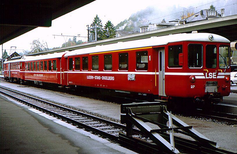
The operating controls of the 1,000 mm (3 ft 3⅜ in) gauge cogwheel electric locomotive BDeh 4/4
view, operating in line
Luzern-Engelberg. The wheel controls motor power, not driving direction.

Electric locomotive used in mining operations in
Flin Flon, Manitoba. This locomotive is on display and not currently in service.
An electric locomotive can be supplied with power from
This is in marked contrast to a Diesel-electric locomotive, which combines an onboard Diesel engine with an electrical power transmission or store (battery, ultracapacitor) system.
The distinguishing design features of electric locomotives are:
- The type of electrical power used, either alternating current or direct current.
- The method for store (batteries, ultracapacitors) or collecting (transmission) electrical power.
- The means used to mechanically couple the traction motors to the driving wheels (drivers).
[edit] Direct or alternating current
The most fundamental difference lies in the choice of direct (DC) or alternating current (AC). The earliest systems used direct current as, initially, alternating current was not well understood. Direct current locomotives typically run at relatively low voltage (600 to 3,000 volts); the equipment is therefore relatively massive because the currents involved are large in order to transmit sufficient power. Power must be supplied at frequent intervals as the high currents result in large transmission system losses.
As alternating current motors were developed, they became the predominant types, particularly on longer routes. High voltages (tens of thousands of volts) are used because this allows the use of low currents; transmission losses are proportional to the square of the current (e.g. twice the current means four times the loss). Thus, high power can be conducted over long distances on lighter and cheaper wires. Transformers in the locomotives transform this power to a low voltage, high current for the motors (the magnet fields, hence power, from the motor is proportional to electric current).[9] A similar high voltage, low current system could not be employed with direct current locomotives because there is no easy way for DC to do the voltage/current transformation so efficiently achieved by AC transformers.
AC traction sometimes uses three phase current rather than the single phase of household use. Speed control of three-phase AC motors remained problematic until the introduction of power electronic control circuits in the 1960s. Italy was the only country to try to solve the problem by using three-phase motors fed by three-phase lines: this system, however, caused other maintenance and technology problems, and was abandoned in the 1970s.
The previous direct commutators had problems at both start and low velocities. Rectifier locomotives, which used AC power transmission and DC motors, were common. Today's advanced electric locomotives have invariably brushless three-phase AC induction motors. These polyphase machines are powered from GTO-, IGCT- or IGBT-based inverters. The cost of electronic devices in a modern locomotive can be up to 50% of the total cost of the vehicle.
Electric traction allows the use of regenerative braking, in which the motors are used as brakes and become generators that transform the motion of the train into electrical power that is then fed back into the lines. This system is particularly advantageous in mountainous operations, as descending locomotives can produce a large portion of the power required for ascending trains.
Most systems have a characteristic voltage, and in the case of AC power a system frequency. Many locomotives over the years were equipped to handle multiple voltages and frequencies as systems came to overlap or were upgraded. American FL9 locomotives were equipped to handle power from two different electrical systems and could also operate as a conventional diesel-electric.
While recently designed systems invariably operate on alternating current, many existing direct current systems are still in use — e.g. in South Africa, and the United Kingdom (750 V and 1,500 V); Netherlands, Mumbai, Ireland (1,500 V); Slovenia, Belgium, Italy, Poland, Russia, Spain (3,000 V), and the cities of Washington DC (750 V).
[edit] Power transmission

A modern
pantograph. The device shown is technically a half-pantograph.
See also Railway electrification system
Electrical circuits require two connections (or for three phase AC, three connections). From the very beginning the trackwork itself was used for one side of the circuit. Unlike model railroads, however, the trackwork normally supplies only one side, the other side(s) of the circuit being provided separately.
The original Baltimore and Ohio Railroad electrification used a sliding shoe in an overhead channel, a system quickly found to be unsatisfactory. It was replaced with a third rail system, in which a pickup (the "shoe") rode underneath or on top of a smaller rail parallel to the main track, somewhat above ground level. There were multiple pickups on both sides of the locomotive in order to accommodate the breaks in the third rail required by trackwork. This system is preferred in subways because of the close clearances it affords.
However, railways generally tend to prefer overhead lines, often called "catenaries" after the support system used to hold the wire parallel to the ground. Three collection methods are possible:
- Trolley pole: a long flexible pole, which engages the line with a wheel or shoe.
- Bow collector: a frame that holds a long collecting rod against the wire.
- Pantograph: a hinged frame that holds the collecting shoes against the wire in a fixed geometry.
Of the three, the pantograph method is best suited for high-speed operation. Some locomotives are equipped to use both overhead and third rail collection(e.g. British Rail Class 92).
[edit] Driving the wheels
During the initial development of railroad electrical propulsion, a number of drive systems were devised to couple the output of the traction motors to the wheels. One of the earliest methods was the jackshaft drive[citation needed]. In this arrangement, the traction motor is mounted within the body of the locomotive and drives the jackshaft through a set of gears. This system was employed because the first traction motors were too large and heavy to mount directly on the axles. Due to the number of mechanical parts involved, frequent maintenance was necessary. The jackshaft drive was abandoned for all but the smallest units when smaller and lighter motors were developed,
Several other systems were devised as the electric locomotive matured. The Buchli drive was a fully-spring loaded system, in which the weight of the driving motors was completely disconnected from the driving wheels. First used in electric locomotives from the 1920s, the Buchli drive was mainly used by the French SNCF and Switzerland's SBB-CFF-FFS. The quill drive was also developed about this time, and mounted the traction motor above or to the side of the axle and coupled to the axle through a reduction gear and a semi-flexible shaft (the quill). The Pennsylvania Railroad GG1 locomotive used a quill drive. Again, as traction motors continued to shrink in size and weight, quill drives gradually fell out of favour.
Another drive example was the "bi-polar" system, in which the motor armature was the axle itself, the frame and field assembly of the motor being attached to the truck (bogie) in a fixed position. The motor had two field poles, which allowed a limited amount of vertical movement of the armature. This system was of limited value since the power output of each motor was limited. The EP-2 bi-polar electrics used by the Milwaukee Road compensated for this problem by using a large number of powered axles.
Modern electric locomotives, like their Diesel-electric counterparts, almost universally use axle-hung traction motors, with one motor for each powered axle. In this arrangement, one side of the motor housing is supported by plain bearings riding on a ground and polished journal that is integral to the axle. The other side of the housing has a tongue-shaped protuberance that engages a matching slot in the truck (bogie) bolster, its purpose being to act as a torque reaction device, as well as a support. Power transfer from motor to axle is effected by spur gearing, in which a pinion on the motor shaft engages a bull gear on the axle. Both gears are enclosed in a liquid-tight housing containing lubricating oil. The type of service in which the locomotive is used dictates the gear ratio employed. Numerically high ratios are commonly found on freight units, whereas numerically low ratios are typical of passenger engines.
[edit] Wheel arrangements

A
GG1 electric locomotive.
The Whyte notation system for classifying steam locomotives is not adequate for describing the varieties of electric locomotive arrangements, though the Pennsylvania Railroad applied classes to its electric locomotives as if they were steam or concatenations of such. For example, the PRR GG1 class indicates that it is arranged like two 4-6-0 class G locomotives that are coupled back-to-back.
In any case, the UIC classification system was typically used for electric locomotives, as it could handle the complex arrangements of powered and unpowered axles, and could distinguish between coupled and uncoupled drive systems.
wikipedia.org


 [Image: London nuked, courtesy of
 [Image: Courtesy of

 [Images: Courtesy of
 [Image: Courtesy of
 [Image: Courtesy of
 [Image: Courtesy of
 [Image: Courtesy of
 [Image: Courtesy of

 A jet engine works like this: It sucks in air from the front of the engine. This air is burned with the fuel within the engine. The resulting large mass of gas is ejected towards the rear at high velocity, which both propels the airplane forward, and gets more air sucked into the engine. In normal flight, the engines are used to propel the airplane _forward_. The actual 'uplift' is gained through the wings using the strong flow of the wind. (How actually the wings lift the airplane is a bit controversial, there is the 'Bernoulli' side, and the 'Newton' side... But that's another story.)
 Rockets can work anywhere, in vacuums, or in the atmosphere. A good example of this would be the space shuttle, which uses both of main types of rocket engines. The large nozzles you see at the bottom of the Shuttle itself and liquid-fueled rocket motors. They spray liquid hydrogen and liquid oxygen together, right at the bottom of the cone, which then burns as long as it continues to be fed fuel and oxygen. The rocket, however, doesn't use any air. It will work at any altitude, or in space. The problem is, though, that now, the craft must not only carry fuel... but it must carry oxygen as well. The huge brown tank on the belly of the Space Shuttle is the main fuel tank, holding both hydrogen and oxygen. To lift all that weight requires a LOT of energy, which requires more fuel, which requires more space, and weight; and at a certain point, using liquid-fueled rockets, you start to work against yourself. You can see how large the Saturn V rockets were compared to the Space Shuttle, and you can compare payloads. This is where the solid rocket boosters come in.

 Step 1 - Stain the Titanium Dioxide with the Natural Dye: Stain the white side of a glass plate which has been
 ). This glass has been previously coated with a transparent conductive layer (SnO
 Step 2 - Coat the Counter Electrode: The solar cell needs both a positive and a negative plate to function. The positive electrode is called the counter electrode and is created from a "conductive" SnO
 Steps 3 & 4 - Add the Electrolyte and Assemble the Finished Solar Cell: The Iodide solution serves as the electrolyte in the solar cell to complete the circuit and regenerate the dye. Place the stained plate on the table so that the film side is up and place one or two drops of the iodide/iodine electrolyte solution on the stained portion of the film. Then place the counter electrode on top of the stained film so that the conductive side of the counter electrode is on top of the film. Offset the glass plates so that the edges of each plate are exposed. These will serve as the contact points for the negative and positive electrodes so that you can extract electricity and test your cell.